Satellite antenna - construction design

  • Two Factor Authentication is now available on BeyondUnreal Forums. To configure it, visit your Profile and look for the "Two Step Verification" option on the left side. We can send codes via email (may be slower) or you can set up any TOTP Authenticator app on your phone (Authy, Google Authenticator, etc) to deliver codes. It is highly recommended that you configure this to keep your account safe.

Varpu

Novice Nali City Reviewer
May 21, 2001
309
0
0
66
Finland
furpile.com
These are renderings of the antenna base design. What do you think ?

Carousel1s.jpg

This is the construction of the antenna base. It has a side-rail to keep it absolutely steady when turning, a spring to take load out of the side rail and a few ball bearings (9 to be exact).

Carousel2s.jpg

This is a close-up of one of the rollers around the base. There are 6 of these and each of them is capable of handling about 400 Kg weight. Each roller has an elastic dampener (nitrile rubber) to take away the small scratches in the rail.

Carousel3s.jpg

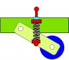
This is the spring that takes away most of the load from the side rail. The ball bearing is more than capable of handling 10 times the load it will ever get in this installation. It was chosen merely by the dimensions than the load capacity.

Carousel4s.jpg

Both upper and lower parts of this carousel are adjustable for off-center conditions. This is essential to be able to straighten things up.

Larger versions of the images available -> 1 2 3 4

Have fun !
 

Varpu

Novice Nali City Reviewer
May 21, 2001
309
0
0
66
Finland
furpile.com
3DSMAX (V4)
Bought it from Moscow about one year ago.
The nice thing in it is that the drawings are accurate and you can export those to AutoCAD if one needs more "technical" drawings.
The scale is in millimeters - I tried to make a static mesh out of this so I would be able to run around the thing but my UED2 crashed because of the huge scale.
 

Twrecks

Spectacularly Lucky
Mar 6, 2000
2,606
10
36
In Luxury
www.twrecks.info
Is the red pole both your pivot and your atenna. the dual ring stanchion is nice but for ease of adjustment the lower jack bolt set should be in-line with the upper set with only four spokes and bolts per ring. More girdles (angled braces) between the upper and lower rails is the place you need strength. An odd number of rollers will also prevent harmonic ocsillations from escillating during use. Last for now, the greatest number of anchors the better for the track. Here's a cheep anchor solution that is adjustable and locks:
 

Attachments

  • JACK.jpg
    JACK.jpg
    49.4 KB · Views: 22

Twrecks

Spectacularly Lucky
Mar 6, 2000
2,606
10
36
In Luxury
www.twrecks.info
Actually I kinda like the six spoke arrangement now that i look at it, but definately go with four jack bolts per ring as you can't slip the pole in a plane with 6. If you want, add an additional 4 for a securing set for a total of 8 for each. But man, I've had to deal with the adjustable stuff many times, and believe me clocking at 90deg for checks is the way to go. Don't forget a means of lubrication for your bearing points, depending on the scale and service life of your rig. I can't tell the true size from the pics.
 

Varpu

Novice Nali City Reviewer
May 21, 2001
309
0
0
66
Finland
furpile.com
You're quite right about the oscillations. Especially if the number of attach points and the number of "wheels" are the same the rail will become "bumby" after some use.

Maybe 7 spoke thing and 9 attachments yielding 7*9 = 63 bumps. Definately smoother than the 6 bumbs now. Using more spokes also allows for lighter material. However - there is an issue with welding as the more welded joints you have the more the thing is likely to get twisted - it takes some skill to put it together without warping it too much :)

Thanks for the attacment picture. It is way better than my "solution".

The carousel is about 2.4 meters in diameter.

Thanks !
 
Last edited:

Twrecks

Spectacularly Lucky
Mar 6, 2000
2,606
10
36
In Luxury
www.twrecks.info
Well the 6 up, seven down would be the easier to manufacter. Spacing 7 leveling pads is sinch and circles lend themselves geometrically to the number 6 every time.
2.4 meters isn't all that big. What type of attena you mounting and where?
 

Varpu

Novice Nali City Reviewer
May 21, 2001
309
0
0
66
Finland
furpile.com
TakenDownSmall.jpg

Parabloid antenna 2.4 metres in diameter. The funny looking cake on top of it is the snow shield. It also takes some of the wind-load away.

It will be sitting on top of solid (ground) rock.

Needless to say - it will be published in the net as soon as I get it working. After that you should be able to pick up polar-circulating satellites (weather satellites with high image resolution).

And - maybe it becomes reserved every evening as my wife starts looking the Bold and The beautiful in all her wisdom :)

The antenna has a very narrow FOV. You can get gain in excess of 60db out of it but after that the aiming is hard stuff. Therefore the basement needs to be very stiff. I have been told that you shoul be able to point it withing 0.5 degrees to get the most out of it.

As I live here high up there are more geostationery satellites withing line of sight that the equator d00ds - the problem is that these are very low in the horizon. Therefore this huge mirror.

I will also attach a 1 GhZ cross-yag into it to be able to receive lower frequencies. The length of this apparatus is about 4 metres. The neighbors will be "delighted" as the antenna has servo motors (3 phase frequency inverter driven) and it sounds lot like the capitol metro. Fortunately the municipal building inspector is a radio-amateur :)
 
Last edited:

Lruce Bee

Transcending to another level
May 3, 2001
1,644
3
38
Sherwood Forest
This is fascinating stuff - both in the project and the skill and dedication in which you are executing it is really quite something - I shall follow this with great interest

Lruce
 

Varpu

Novice Nali City Reviewer
May 21, 2001
309
0
0
66
Finland
furpile.com
Changed the design (and the renderings accordingly).
Very Many Thanks to our Big Lizard for good suggestions.
However - I decided to make the rail attaching rods of a different design and this is the reason why:
Since the thing is going to sit on top of hard rock (granite) and since the surface of the rock is "soft" it will be nessecary to bolt these rods deep inside the rock.
The method is simple - you just make a thing that spreads when you hammer it down into a hole (40 centimeters deep). After it has been hammered into there You need dynamite to get the rod out of there.
Then you just cut the rod and make the thread on top of it.
 

Twrecks

Spectacularly Lucky
Mar 6, 2000
2,606
10
36
In Luxury
www.twrecks.info
I think you are overkill on your anchoring, 1 rod per foot is more than enough IMO, and mb 6 for your central spar. I'm used to much heavier equipment and typically we only use 4 anchors for anything under 30,000 lbs. In machine tools, controlling vibration is a key issue. As a shameless self pimpage, here's a pic of my current project. The smaller/shorter version we sold 40 units last month and already sold everything we can build through the end of the year:
 

Attachments

  • TL2.jpg
    TL2.jpg
    117.2 KB · Views: 22

Twrecks

Spectacularly Lucky
Mar 6, 2000
2,606
10
36
In Luxury
www.twrecks.info
Hmm. I think I see what you're trying to achieve with 2 lag bolts per foot, correct me if I'm wrong, this appears to be a means you can take out twist in the rail.
With the added suspension on the outer rollers, I don't see a need for the big spring. You want weight transfer to the ring for stability, lessening that will make the entire system easy to deflect. Plus slipping the big bearing on the spar means built in gap, might as well have a bushing there instead (aluminum-broze alloy works nice but not the cheapest solution and is for really big loads). Your suspension on the trucks lacks adjustment aswell. Sorry dOOd.
here's an idea for a simple suspension, the side pivot plates could be made larger to stradle the trak:
 

Attachments

  • suspension.jpg
    suspension.jpg
    32.3 KB · Views: 8

Varpu

Novice Nali City Reviewer
May 21, 2001
309
0
0
66
Finland
furpile.com
Twrecks said:
<snip> ... Your suspension on the trucks lacks adjustment aswell. Sorry dOOd.

There's absolutely nothing to be sorry about - I'm a programmer you know. Machinery is merely just a hobby for me. And, if I wouldn't need advice I wouldn't be publishing this here. In technical means that construction must be a peice of carp. Critics is exactly what I'm after here.

Overkill - maybe. But if I'm going to get anywhere near stable when that big antenna is put on top of the thing it better be steady. That antenna acts like a big sail - it can generate huge (in excess of 2000 kilograms) windloads @ 25 m/sec. It is very often it blows that much here. It would be shame to have this defunct every time we have a freshening blow outside. When it becomes storm - and that is not too rare either we get winds easily topping above 40 metres/second. Although that does not seem like much as compared to hurricane/taiphun they occur each and every year. Collecting the remains of the antenna annually from the neighboring field is a no-go.

Your roller design is absolutely better and it also has the adjustment as You stated. It also seems to be easier to manufacter and looks like it would be easier to swap broken bearings etc there.

The 2 leg design is reallt there to take the twist away.

About your self-pimping machinery. I'd like to have one of those attached to my computer. I have a "manual" version (40 years old) in my carage and it is NOT collecting dust. Yeah - the vibration can be an issue - especially if you are handling stainless steel. I made a pair of candle holders out of that material for my mother in law (just because she liked the look of it) and man - was that hard stuff....
 
Last edited:

Varpu

Novice Nali City Reviewer
May 21, 2001
309
0
0
66
Finland
furpile.com
Twrecks said:
I'd like to see what you have planned for a drive and position feedback.

The drive will be two 3-phase induction motors driven by a frequency converter. Although stepper motors would be easier to use they make a lot of noise and also strain the drive a lot more. The induction motor design is a lot smoother.

Feedback is achieved using an optical angle decoder and a fixed index. The position of the index is irrelevant as long as it is always the same. Same goes to the angle/pulse ratio as long as it is linear. Both are easy to do. Rest of the control logic goes into a black box wich is used to feed the motors, input the angle pulses and user data via RS cable (twisted pair, current driven RS-48?). The actual computation of the movement is calculated in the control computer (yeah, this involves some programming).
 
Last edited: