
Modelling a realistic weapon
Tutorial copied with the friendly permission from Identity Crisis .
Created by MoRPHeuss - Website: Titaniumfrag .
Welcome to the first Titaniumfrag modelling tutorial. I am going to show you as best I can how to model a realistic, low polygon gun. This would be ideal for weapon models for games like Quake, UT or Half-Life. You will need a version of 3D Studio Max, and a lot of patience. Modelling takes time, but if you work at it, you can create stunning results. This tutorial is aimed at intermediate users, so I assume you know most of the basics of Max such as viewport control and object creation. Remember to save frequently, whatever you are doing. There's nothing more annoying that completing a complicated piece of a model only to have 3DS Max crash out for no good reason. Don't rely on Max's auto-backup feature - it sometimes doesn't save the whole scene.
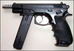
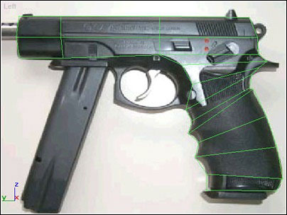
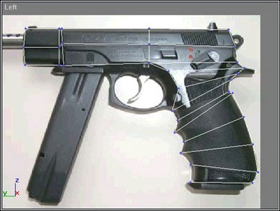
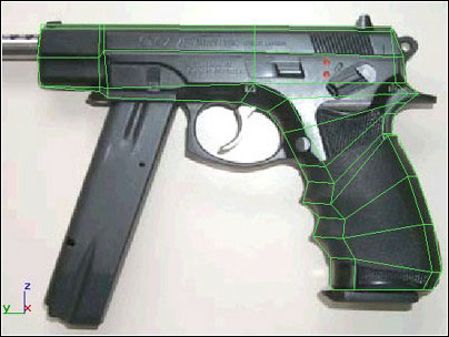
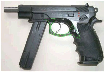
1. Find a good quality side-on photo of the gun you want to model.
SecurityArms is a great site for pictures of guns, and I will be using a picture from the site as a basis for this tutorial.
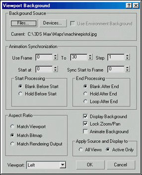
2. Once you have found a good picture, open 3DS Max. Select the "Left" viewport and hit ALT-B. This should bring up the Viewport Background properties window. What we are aiming to do is use the image we got as a background to model over. I find this very easy when modelling weapons, because it produces accurate results, and you can use the image as a texture too! Click the "Files" button and locate the picture you saved. Change the Aspect Ratio to "Match Bitmap" and then check the "Lock Zoom/Pan" tickbox. This means that if you pan (move) the viewport around, the image will follow the movement so your model will be locked in place.
3. Try moving the viewport around (hold down the middle mouse button, or click the Pan Viewports button in the bottom right of your screen). See if the image moves as the viewport does. Try zooming in as well, using the scroll wheel on your mouse or the Zoom Viewports button in the bottom right of your screen. All of the viewport controls are in the bottom right of the default Max configuration.
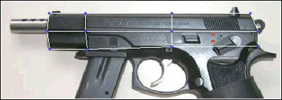
4. Now we can start the actual modelling process. Create a box in the "Left" viewport. Drag it out so that it roughly fits the size of the gun barrel. Have a look at the shape of the gun, and decide how many segments you will need to add a decent amount of detail. You don't need any Height segments, as we are going to mirror the half of the gun to make a whole gun. This saves time, and it doesn't clutter up the screen while you create the main shape of the gun. The box I created (I'll be using Max default units throughout the tutorial) was Length=52.0, Width=300.0, Height=25.0, with Segments of L=2, W=3, H=1. I positioned it at XYZ=0,-15,93. To achieve exact positioning, right-click on the Move, Rotate or Scale icons to bring up the Transform Type-In window.
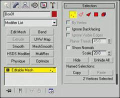
5. Now we need to go from the simple box to a more complicated mesh. The first step is to make the box into an Editable Mesh. Go to the Modify panel to the right of the screen, and right-click on "Box". A drop-down menu should appear, select "Convert to: Editable Mesh" from the menu. Now you can control the vertices and faces of the mesh - these are known as "Sub-objects". However, bear in mind that when you convert a primitive model in this way, you lose the type-in parameters for controlling the size and segments of the object.
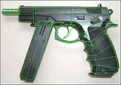
6. We can now start editing the vertices on the mesh to amend the shape of the box. In the Modify panel, you will see 5 little red icons. They are, respectively: Vertex, Edge, Face, Polygon and Element sub-object controllers. Click the Vertex button. Now you can edit the vertices. First, select the vertices in the "Left" viewport at the top right of the box and move them so they match the outline of the gun more closely. Don't worry about little fiddly details yet, just try to get the main shape of the gun. Continue moving the vertices until they look something like this:
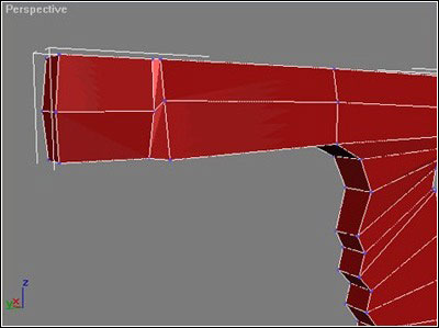
7. Now we can extrude some faces to make the shape more detailed. To see the faces more clearly, right-click on the "Perspective" viewport in the top left corner. This brings up a menu with the viewing options. Click "Edged faces". You can now see the edges of each polygon making up the box. Click the "Polygon" sub-object button in the Modify panel to begin editing faces. Select the far-right polygon on the bottom of the box. This will become the gun handle grip. The Extrude button is handy for adding details that stick out of an object. It basically just pulls the face outwards from the model. After each extrusion, press Enter, so that the next extrude you do will make a new segment. When you make a new extrusion, try clicking and dragging up or down on the little arrows on the right of the type-in box. This drags the extrusion out so you can see how far each value takes the new segment. To make the entire handle for the gun, I extruded with values of: 10, 10, 40, 15, 15, 17, 20, 22, 20. This took into account all the contours on the handle of the gun, so that the vertices will fit when they are moved.
8. You should now have a very angular and straight box sticking out from your original mesh. Go back into Vertex sub-object mode, and drag the vertices to fit the shape of the handle in the image. Mine ended up looking like this:
9. You may have noticed that the shadows on the front of the gun barrel indicate that the barrel goes inward near the end. To model this effect, you should select all the front 6 vertices and move them back so they are very close to the next 6 in line. Go into Face sub-object mode, and extrude the front 2 faces to the end of the barrel again. Switch back to Vertex editing and move the outer vertices inwards a bit, so it looks like this :
10. Now to make the gun look more rounded. Select the vertices on the outside of the front of the handle. Move them all in by about 20 units, or until it looks right. Also, move the back outer vertices inwards a bit too. Then select the inner bottom vertices of the main gun, and move them down until they fit with the shape of the gun. Your mesh in the left viewport should now look like this:
11. The gun needs a cylindrical end to the barrel, as you can see on the image. Create a cylinder in the Front viewport. Mine had Radius=10, Height=-55, Height Segments=1, Cap Segments=1 and Sides=12. I put it's position at XYZ=0,130,101. Remember we are only modelling half a gun, so we should delete the vertices on the unwanted side. Convert the cylinder to Editable Mesh, go to the Vertex sub-object level and select the vertices we won't be needing. Press "Delete". Now you can attach the new cylinder to the main mesh. Select the main gun mesh, and go to the Modify panel. Click "Attach" in the Edit Geometry rollout. This function attaches other meshes to the mesh you have selected. After clicking Attach, click on your new cylinder. It becomes part of the main gun mesh.
12. Now to make the large ammo clip near the front of the gun. This is easy. Create a new box in the left viewport, mine had Length=190, Width=55, Height=18, L-Segs=1, W-Segs=2, H-Segs=1. Convert the new box to Editable Mesh. Now, move the vertices to match the shape of the magazine, and bring in the outer vertices a bit to bevel the magazine slightly. Attach this box to the main gun model.
13. Now to create the trigger and trigger-guard. Make a new box, L/W/H=10,90,10. LS/WS/HS=1,8,1. I positioned it at XYZ=0,-30,2.5. Convert to Editable Mesh, then go into Vertex sub-object mode. Move the vertices until they match the outline of the trigger guard roughly. Select the lower outer vertices and move them upwards a bit. Select the upper outer vertices and move them down a bit. This gives the trigger guard it's "bevelled" look.
14. I made the trigger as a box in the "Left" viewport, with it's L/W/H=40,10,8, and LS/WS/HS=4,1,1. I positioned it at XYZ=0,-32,36. Convert it to Editable Mesh, then move the vertices to match the outline of the trigger. Bevel the trigger using the same method as with the trigger guard, try to match the highlights with the bevel to give a more authentic look. Attach it to the mesh, unless you want to leave it as a separate moving part. The gun should now be looking like this:
15. Delete all the back-faces along X=0. This is to reduce the polycount when you weld the two mirrored segments together, and you will never see these faces anyway.
16. Congratulations! You now have half a gun! Select the model and go to the "Tools" menu. Select "Mirror" with the Front Viewport active. Select Mirror Axis: X and Clone Selection: Copy. The gun half is now mirrored to make a whole gun! How simple.
17. Now to make it all one big seamless mesh. Select the first half of the gun, and Attach the other half you just mirrored. Now, to make it all seamless, go to Vertex sub-object mode. Select all of the vertices in the middle (where X=0). You will probably have about 140 vertices if you followed my instructions...don't worry if it's not. Now, in the Edit Geometry rollout of the editable mesh, press the "Selected" button under "Weld". The number of selected vertices should now be roughly, if not exactly, half the previous number. Now the mesh is seamless! Save the file.
18. Add any fiddly bits such as sights/buttons. Just make boxes or cylinders and tweak the vertices until they fit. I do this after mirroring the mesh, usually. Attach them to the main mesh as usual.
19. Now, to smooth the gun, go to the Modify panel with your mesh selected. Select "Smooth" from the modifier list, check the "Auto Smooth" box, and set the threshold to about 65. This will make the gun look nice and smooth. Feel free to tweak the value until the gun looks right.
20. Now to apply a quick texture. This makes the gun look a lot more realistic. In the "Left" viewport with your mesh selected, go to the modify panel and select "UVW Map" from the modifier list. You will see an orange box surround your model. This is the extent of the map. Click "Region Fit", and drag the box until it encompasses the whole of the "Left" viewport background image. Now you can make and apply a texture. Open up the Material Editor. Click the empty button to the right of the "Diffuse" colour box. This brings up a list of maps you can use. You want a "Bitmap". Double click this option, and then select the image that you are using as your viewport background for this bitmap. Click the "Show Map in Viewport" button, and then click the "Assign material to selection" button, with your mesh selected. You should see a texture in the Perspective viewport! It should look good enough for the time being - if not you can modify the bitmap's positioning using the "Offset" and "Tile" settings until it fits. I will cover the finer points of skinning for in-game models in a different tutorial...until then, That's all, folks!
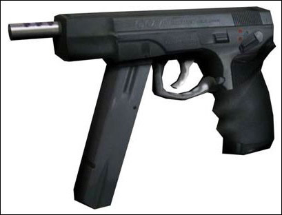
Finished! Here is a render of the model I made while writing this tutorial. It is missing a few details - like sights, and the texture isn't exactly brilliant, but with a bit of work you wouldn't mind seeing it in a game! The final model, after using the Optimise modifier (this can screw up the texture coordinates, so it's best to optimise before texturing) was 386 triangles. This is quite low, considering some modern games can use up to 800 triangles per weapon!
Tutorial copied with the friendly permission from Identity Crisis .
Created by MoRPHeuss - Website: Titaniumfrag .
Welcome to the first Titaniumfrag modelling tutorial. I am going to show you as best I can how to model a realistic, low polygon gun. This would be ideal for weapon models for games like Quake, UT or Half-Life. You will need a version of 3D Studio Max, and a lot of patience. Modelling takes time, but if you work at it, you can create stunning results. This tutorial is aimed at intermediate users, so I assume you know most of the basics of Max such as viewport control and object creation. Remember to save frequently, whatever you are doing. There's nothing more annoying that completing a complicated piece of a model only to have 3DS Max crash out for no good reason. Don't rely on Max's auto-backup feature - it sometimes doesn't save the whole scene.
1. Find a good quality side-on photo of the gun you want to model.
SecurityArms is a great site for pictures of guns, and I will be using a picture from the site as a basis for this tutorial.
2. Once you have found a good picture, open 3DS Max. Select the "Left" viewport and hit ALT-B. This should bring up the Viewport Background properties window. What we are aiming to do is use the image we got as a background to model over. I find this very easy when modelling weapons, because it produces accurate results, and you can use the image as a texture too! Click the "Files" button and locate the picture you saved. Change the Aspect Ratio to "Match Bitmap" and then check the "Lock Zoom/Pan" tickbox. This means that if you pan (move) the viewport around, the image will follow the movement so your model will be locked in place.
3. Try moving the viewport around (hold down the middle mouse button, or click the Pan Viewports button in the bottom right of your screen). See if the image moves as the viewport does. Try zooming in as well, using the scroll wheel on your mouse or the Zoom Viewports button in the bottom right of your screen. All of the viewport controls are in the bottom right of the default Max configuration.
4. Now we can start the actual modelling process. Create a box in the "Left" viewport. Drag it out so that it roughly fits the size of the gun barrel. Have a look at the shape of the gun, and decide how many segments you will need to add a decent amount of detail. You don't need any Height segments, as we are going to mirror the half of the gun to make a whole gun. This saves time, and it doesn't clutter up the screen while you create the main shape of the gun. The box I created (I'll be using Max default units throughout the tutorial) was Length=52.0, Width=300.0, Height=25.0, with Segments of L=2, W=3, H=1. I positioned it at XYZ=0,-15,93. To achieve exact positioning, right-click on the Move, Rotate or Scale icons to bring up the Transform Type-In window.
5. Now we need to go from the simple box to a more complicated mesh. The first step is to make the box into an Editable Mesh. Go to the Modify panel to the right of the screen, and right-click on "Box". A drop-down menu should appear, select "Convert to: Editable Mesh" from the menu. Now you can control the vertices and faces of the mesh - these are known as "Sub-objects". However, bear in mind that when you convert a primitive model in this way, you lose the type-in parameters for controlling the size and segments of the object.
6. We can now start editing the vertices on the mesh to amend the shape of the box. In the Modify panel, you will see 5 little red icons. They are, respectively: Vertex, Edge, Face, Polygon and Element sub-object controllers. Click the Vertex button. Now you can edit the vertices. First, select the vertices in the "Left" viewport at the top right of the box and move them so they match the outline of the gun more closely. Don't worry about little fiddly details yet, just try to get the main shape of the gun. Continue moving the vertices until they look something like this:
7. Now we can extrude some faces to make the shape more detailed. To see the faces more clearly, right-click on the "Perspective" viewport in the top left corner. This brings up a menu with the viewing options. Click "Edged faces". You can now see the edges of each polygon making up the box. Click the "Polygon" sub-object button in the Modify panel to begin editing faces. Select the far-right polygon on the bottom of the box. This will become the gun handle grip. The Extrude button is handy for adding details that stick out of an object. It basically just pulls the face outwards from the model. After each extrusion, press Enter, so that the next extrude you do will make a new segment. When you make a new extrusion, try clicking and dragging up or down on the little arrows on the right of the type-in box. This drags the extrusion out so you can see how far each value takes the new segment. To make the entire handle for the gun, I extruded with values of: 10, 10, 40, 15, 15, 17, 20, 22, 20. This took into account all the contours on the handle of the gun, so that the vertices will fit when they are moved.
8. You should now have a very angular and straight box sticking out from your original mesh. Go back into Vertex sub-object mode, and drag the vertices to fit the shape of the handle in the image. Mine ended up looking like this:
9. You may have noticed that the shadows on the front of the gun barrel indicate that the barrel goes inward near the end. To model this effect, you should select all the front 6 vertices and move them back so they are very close to the next 6 in line. Go into Face sub-object mode, and extrude the front 2 faces to the end of the barrel again. Switch back to Vertex editing and move the outer vertices inwards a bit, so it looks like this :
10. Now to make the gun look more rounded. Select the vertices on the outside of the front of the handle. Move them all in by about 20 units, or until it looks right. Also, move the back outer vertices inwards a bit too. Then select the inner bottom vertices of the main gun, and move them down until they fit with the shape of the gun. Your mesh in the left viewport should now look like this:
11. The gun needs a cylindrical end to the barrel, as you can see on the image. Create a cylinder in the Front viewport. Mine had Radius=10, Height=-55, Height Segments=1, Cap Segments=1 and Sides=12. I put it's position at XYZ=0,130,101. Remember we are only modelling half a gun, so we should delete the vertices on the unwanted side. Convert the cylinder to Editable Mesh, go to the Vertex sub-object level and select the vertices we won't be needing. Press "Delete". Now you can attach the new cylinder to the main mesh. Select the main gun mesh, and go to the Modify panel. Click "Attach" in the Edit Geometry rollout. This function attaches other meshes to the mesh you have selected. After clicking Attach, click on your new cylinder. It becomes part of the main gun mesh.
12. Now to make the large ammo clip near the front of the gun. This is easy. Create a new box in the left viewport, mine had Length=190, Width=55, Height=18, L-Segs=1, W-Segs=2, H-Segs=1. Convert the new box to Editable Mesh. Now, move the vertices to match the shape of the magazine, and bring in the outer vertices a bit to bevel the magazine slightly. Attach this box to the main gun model.
13. Now to create the trigger and trigger-guard. Make a new box, L/W/H=10,90,10. LS/WS/HS=1,8,1. I positioned it at XYZ=0,-30,2.5. Convert to Editable Mesh, then go into Vertex sub-object mode. Move the vertices until they match the outline of the trigger guard roughly. Select the lower outer vertices and move them upwards a bit. Select the upper outer vertices and move them down a bit. This gives the trigger guard it's "bevelled" look.
14. I made the trigger as a box in the "Left" viewport, with it's L/W/H=40,10,8, and LS/WS/HS=4,1,1. I positioned it at XYZ=0,-32,36. Convert it to Editable Mesh, then move the vertices to match the outline of the trigger. Bevel the trigger using the same method as with the trigger guard, try to match the highlights with the bevel to give a more authentic look. Attach it to the mesh, unless you want to leave it as a separate moving part. The gun should now be looking like this:
15. Delete all the back-faces along X=0. This is to reduce the polycount when you weld the two mirrored segments together, and you will never see these faces anyway.
16. Congratulations! You now have half a gun! Select the model and go to the "Tools" menu. Select "Mirror" with the Front Viewport active. Select Mirror Axis: X and Clone Selection: Copy. The gun half is now mirrored to make a whole gun! How simple.
17. Now to make it all one big seamless mesh. Select the first half of the gun, and Attach the other half you just mirrored. Now, to make it all seamless, go to Vertex sub-object mode. Select all of the vertices in the middle (where X=0). You will probably have about 140 vertices if you followed my instructions...don't worry if it's not. Now, in the Edit Geometry rollout of the editable mesh, press the "Selected" button under "Weld". The number of selected vertices should now be roughly, if not exactly, half the previous number. Now the mesh is seamless! Save the file.
18. Add any fiddly bits such as sights/buttons. Just make boxes or cylinders and tweak the vertices until they fit. I do this after mirroring the mesh, usually. Attach them to the main mesh as usual.
19. Now, to smooth the gun, go to the Modify panel with your mesh selected. Select "Smooth" from the modifier list, check the "Auto Smooth" box, and set the threshold to about 65. This will make the gun look nice and smooth. Feel free to tweak the value until the gun looks right.
20. Now to apply a quick texture. This makes the gun look a lot more realistic. In the "Left" viewport with your mesh selected, go to the modify panel and select "UVW Map" from the modifier list. You will see an orange box surround your model. This is the extent of the map. Click "Region Fit", and drag the box until it encompasses the whole of the "Left" viewport background image. Now you can make and apply a texture. Open up the Material Editor. Click the empty button to the right of the "Diffuse" colour box. This brings up a list of maps you can use. You want a "Bitmap". Double click this option, and then select the image that you are using as your viewport background for this bitmap. Click the "Show Map in Viewport" button, and then click the "Assign material to selection" button, with your mesh selected. You should see a texture in the Perspective viewport! It should look good enough for the time being - if not you can modify the bitmap's positioning using the "Offset" and "Tile" settings until it fits. I will cover the finer points of skinning for in-game models in a different tutorial...until then, That's all, folks!
Finished! Here is a render of the model I made while writing this tutorial. It is missing a few details - like sights, and the texture isn't exactly brilliant, but with a bit of work you wouldn't mind seeing it in a game! The final model, after using the Optimise modifier (this can screw up the texture coordinates, so it's best to optimise before texturing) was 386 triangles. This is quite low, considering some modern games can use up to 800 triangles per weapon!